

Technical Datasheet: EGE SDN 552/1 GPP
Model/Type: SDN 552/1 GPP
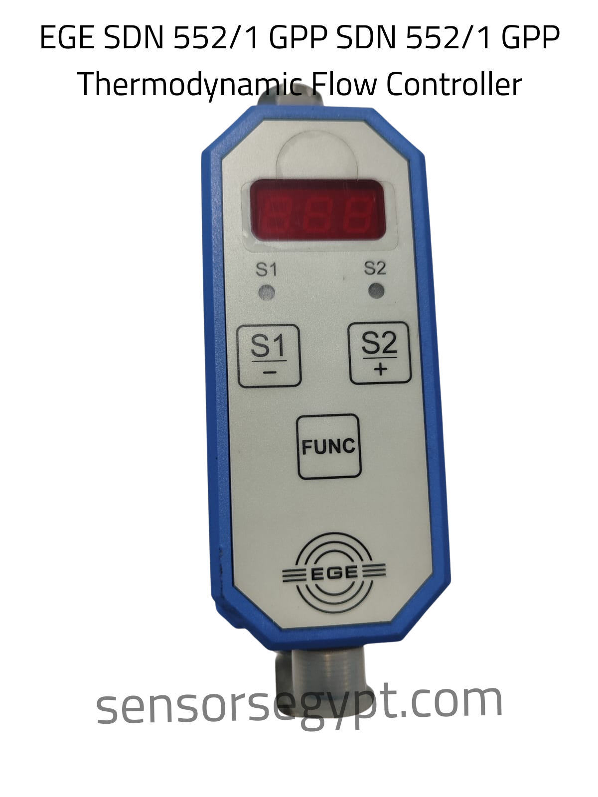
Product Category: Thermodynamic Flow Controller / Monitor (Strömungswächter)
1. Product Characteristics & Application
-
Sensor Type: Inline Thermodynamic Flow Sensor
-
Application Range: Monitoring and precise regulation of liquid media flow rates (e.g., water, glycol mixtures, or low-viscosity oils) within cooling circuits, dosing lines, and industrial pump protection systems.
-
Display & Interface: Integrated front panel featuring a 3-digit LED display, status LEDs for outputs (S1 / S2), and programming push-buttons (S1/-, S2/+, FUNC) for adjusting limit thresholds, calibration, and response parameters in the field.
2. Electrical Data
-
Operating Voltage: 24 V DC (± 10%)
-
Electrical Design: DC PNP
-
Output Configuration: Dual Switching Outputs (S1 + S2)
-
Current Consumption: < 100 mA (idle)
-
Reverse Polarity Protection: Yes
-
Short-Circuit Protection (SCP): Yes
3. Outputs & Signal Rating
-
Output Function: Configurable per channel (S1 and S2 can be individually set to Normally Open or Normally Closed limits via the display interface).
-
Permanent Current Rating (Ie): 200 mA max. per output path.
4. Mechanical & Environmental Data
-
Process Connection: Robust compression fitting union connections at both ends (designed for high-pressure inline fluid networks).
-
Materials: * Housing Block: Heavy-duty industrial polymer (PBT)
-
Wetted Fluid Path: High-grade Stainless Steel (316L / 1.4571 or equivalent)
-
-
Ambient Operating Temperature: -20…70 °C
-
Medium Fluid Temperature Range: 0…85 °C
-
Manufacturer: EGE-Elektronik Spezial-Sensoren GmbH (Germany)
-
Production Code: 35 15/K
5. Electrical Connection & Wiring Layout
The controller features an integrated standard male connector socket at the base for multi-core field cable interfacing.
Pinout Assignment & Color Codes:
-
Pin 1 (BN – Brown): → L+ (24 V DC Positive Power Supply)
-
Pin 2 (WH – White): → S2 Switching Output Channel (PNP signal to Load)
-
Pin 4 (BK – Black): → S1 Switching Output Channel (PNP signal to Load)
-
Pin 3 (BU – Blue): → L- (0 V Ground / Common Negative)
Wiring Layout:
       [ Pin 1 / BN ] ───────────────────────────────────── ( + 24 V DC )
                        │                  │
                 ┌──────┴──────┐    ┌──────┴──────┐
                 │  Output S1  │    │  Output S2  │
                 │ (PNP Signal)│    │ (PNP Signal)│
                 └──────┬──────┘    └──────┬──────┘
                        │                  │
       [ Pin 4 / BK ] ──┘                  └─── [ Pin 2 / WH ] ─── [ Load ] ──┐
         (Load S1)                                (Load S2)                   │
                                                                              ▼
       [ Pin 3 / BU ] ────────────────────────────────────────────────────────┴─── ( 0 V )

DATA SHEET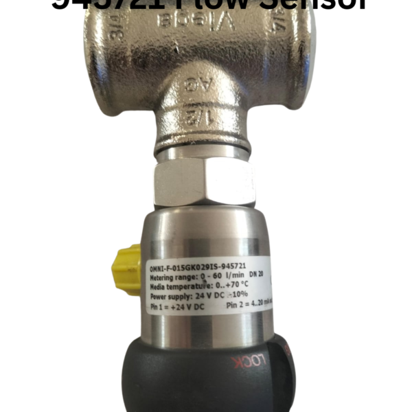
Reviews
There are no reviews yet.