
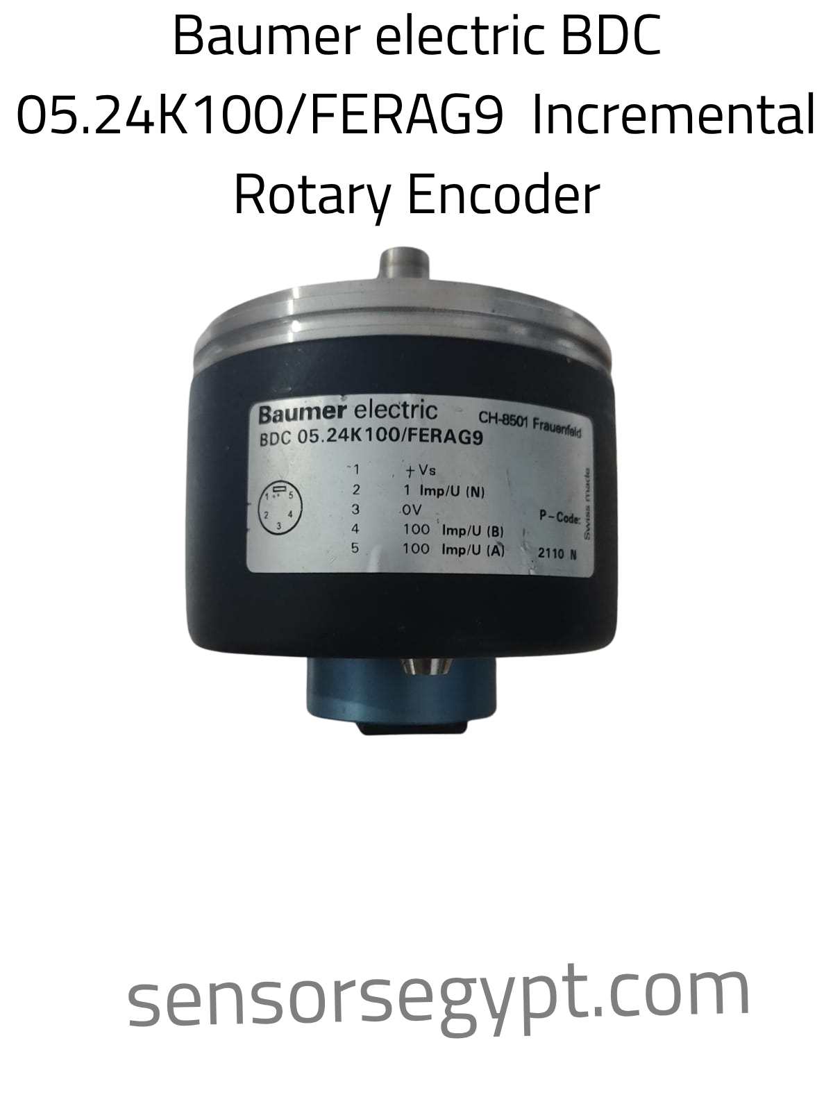
Technical Datasheet: Baumer electric BDC 05.24K100/FERAG9
Model Designation: BDC 05.24K100/FERAG9
System Part Number (Ferag Reference): Ferag 5.690.549
Product Category: Incremental Rotary Encoder (Drehgeber)
Manufacturer Location: CH-8501 Frauenfeld, Switzerland
1. Product Characteristics & Application
-
Sensor Type: Optical Incremental Rotary Encoder.
-
Resolution / Pulses per Revolution (PPR): 100 PPR (100 Imp/U).
-
Special Hardware Build: Customized “FERAG” series build. This specialized industrial version is widely integrated into high-speed printing presses, bindery systems, newspaper conveyor lines, and heavy-duty paper processing equipment designed by the Ferag group.
-
Housing Design: Solid shaft cylindrical metal housing featuring a rear axial output port. It is built with high mechanical robustness to resist extreme vibration, belt pull, and axial loads.
2. Electrical Data
-
Supply Voltage ($+V_s$): Standard automated industrial control system supply voltage compatible with PLC and motion controller input cards.
-
Signals & Output Channels:
-
Channel A: 100 pulses per revolution (100 Imp/U A)
-
Channel B: 100 pulses per revolution (100 Imp/U B)
-
Index Channel (N): 1 reference index pulse per revolution (1 Imp/U N)
-
-
Common Ground / Reference: 0V reference line
3. Performance & Dynamic Protection
-
Data Integrity: High-precision real-time tracking with high noise immunity over signal paths.
-
Vibration and Shock Immunity: Rugged housing design engineered to maintain precision in high-speed, dynamic manufacturing environments.
-
Sealing Protection: Sealed design optimized to protect internal optical discs and electronics from paper dust, oil, and moisture ingress.
4. Mechanical Data
-
Shaft Type: Solid metal drive shaft.
-
Connection Profile: Integrated robust connector pins arrayed inside a heavy-duty physical socket.
-
Housing Material: Heavy-duty aluminum and steel composite casing.
-
Weight: 230 grams
-
Manufacturing Tracking Code: P-Code: 2110 N (indicating production details).
5. Electrical Connection & Pinout Assignment
The encoder features a dedicated 5-pin circular connector socket layout. The pinout configuration is clearly marked on the side label of the casing:
Pin Mapping Table:
| Pin Number | Signal Name on Label | Function Description |
| Pin 1 | +Vs | Positive Power Supply Input |
| Pin 2 | 1 Imp/U (N) | Reference Index Pulse Channel |
| Pin 3 | 0V | Signal Ground / Common Reference |
| Pin 4 | 100 Imp/U (B) | Pulse Channel B Output |
| Pin 5 | 100 Imp/U (A) | Pulse Channel A Output |
On-Body Pin Arrangement diagram:
Plaintext
          (Rear Connector View)
                  [Pin 1]
                 ( + Vs )
                   *
         [Pin 5]       [Pin 2]
       (100 Imp A)   (1 Imp N)
          *             *

         [Pin 4]       [Pin 3]
       (100 Imp B)     ( 0V )
          *             * DATA SHEET


Reviews
There are no reviews yet.