
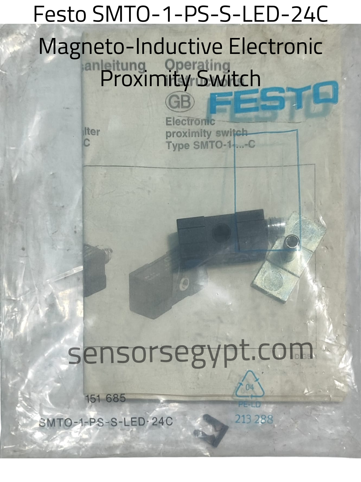
echnical Datasheet: Festo SMTO-1-PS-S-LED-24C
Part Number / Manufacturer Number: 151 685
Product Category: Magneto-Inductive Electronic Proximity Switch (Block Construction)
1. Product Characteristics & Application
-
Sensor Type: Magnetic Field / Cylinder Proximity Sensor
-
Measuring Principle: Magneto-inductive (designed to contactlessly sense the position of the internal piston magnet on pneumatic cylinders).
-
Housing Design: Block construction / rectangular block design (fitted via cylinder tie rods, profile slots, or external mounting kit rods like the bar piece shown next to the sensor).
-
Special Features: Free of copper, PTFE, and silicone. Features an integrated high-visibility LED indicator window for immediate switching status awareness. Highly utilized across heavy industrial automation networks for end-position control and intermediate travel verification on standards-compliant pneumatic cylinders (e.g., Festo DNG, DGO, and DZH series).
2. Electrical Data
-
Operating Supply Voltage: 10…30 V DC (Commonly 24 V DC system integration)
-
Max Output Current: 200 mA
-
Electrical Design / Output Type: DC PNP
-
Switching Element Function: Normally Open (N.O.) Contact
-
Approvals: CE Mark, RCM Mark
3. Performance & Protection Data
-
Ambient Temperature Range: -25 °C to 70 °C
-
Short-Circuit & Overload Protection: Yes
-
Reverse Polarity Protection: Yes
-
Switching Frequency: Highly responsive cyclic performance optimized for precise high-speed pneumatic process feedback loops.
4. Mechanical & Environmental Data
-
Housing Material: Rugged industrial composite engineering polymer / anodized metal mounting paths
-
Dimensions: 50 mm × 10 mm × 10 mm (Compact block frame profile)
-
Weight: 0.03 kg
-
Included Components: 1 x proximity switch, 1 x physical mounting manual sheet, metal fixation hardware, and a small black retaining clip/accessory (visible at the bottom).
5. Electrical Connection & Wiring Layout
The sensor features an integrated quick-connect male plug interface terminal (M8 × 1 thread, 3-pin setup), visible protruding from the right side of the physical block.
Pinout Connection Mapping:
-
Pin 1: Brown wire reference (BN) → + (10…30 V DC Power Supply Input)
-
Pin 4: Black wire reference (BK) → Output Switching Signal (N.O. to Load)
-
Pin 3: Blue wire reference (BU) → – (0 V Ground / Common reference)
Wiring Diagram:
       [ Pin 1 / BN ] ───────────────────────── ( + )
              │
          ┌───┴───┐
          │  PNP  │───────── [ Pin 4 / BK ] ──── [ Load ] ────┐
          │  N.O. │                                          │
          └───┬───┘                                          │
              │                                              │
       [ Pin 3 / BU ] ───────────────────────────────────────┴─── ( - )
DATA SHEET

Reviews
There are no reviews yet.