

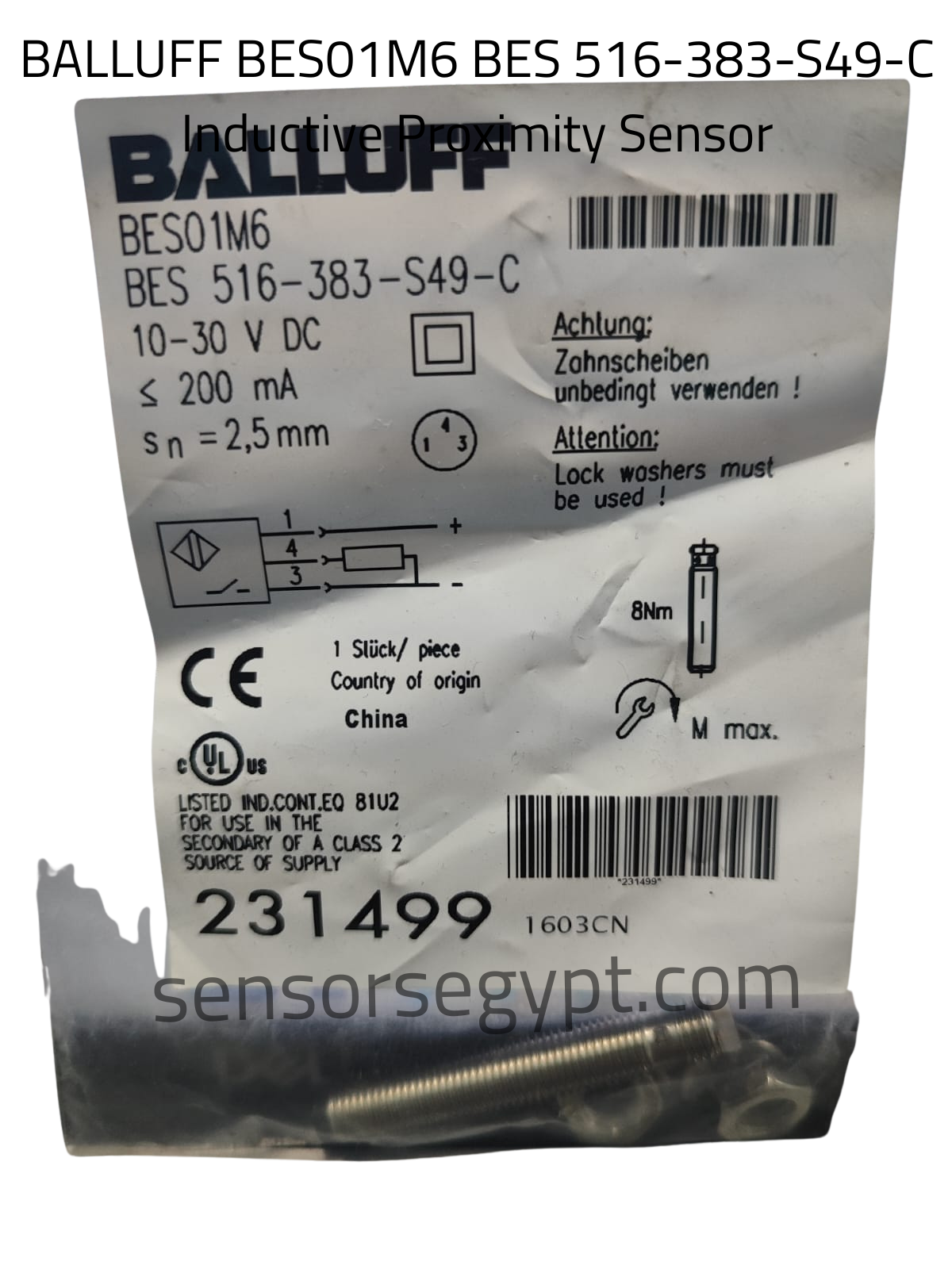
Technical Datasheet: BALLUFF BES01M6
Ordering Code: BES01M6
Part Number / Model: BES 516-383-S49-C
Product Category: Inductive Proximity Sensor
1. Product Characteristics & Application
-
Sensor Type: Inductive Proximity Sensor
-
Housing Design: Threaded mini cylindrical barrel type (M8 × 1).
-
Sensing Range (sn): 2.5 mm (Extended sensing range for an M8 housing size).
-
Mounting: Non-flush mountable (indicated by the extended non-flush range for M8 size and target mechanical specifications).
-
Special Installation Note: As highlighted prominently on the label (Attention: Lock washers must be used! / Achtung: Zahnscheiben unbedingt verwenden!), the included serrated lock washers must be fitted during installation to maintain tight thread locking under mechanical vibration.
-
Tightening Torque: Maximum tightening mechanical limit is 8 Nm.
2. Electrical Data
-
Operating Voltage: 10…30 V DC (Supply for use in the secondary of a Class 2 source of supply)
-
Rated Current Consumption: ≤ 200 mA
-
Electrical Design: DC PNP
-
Output Function: Normally Open (NO)
-
Approvals: CE, cULus Listed (IND. CONT. EQ. 81U2)
3. Performance & Dynamic Data
-
Short-Circuit Protection (SCP): Yes
-
Overload & Reverse Polarity Protection: Yes
-
Switching Frequency: High response cyclic switching velocity optimized for fast-moving target tracking, compact robotic frames, and precision positioning loops.
4. Mechanical & Environmental Data
-
Dimensions: M8 × 1 mm standard metric thread / Full metal threaded shaft
-
Housing Material: High-grade robust metal construction
-
Country of Origin: China (As indicated on label: Country of origin: China)
-
Item Code / Batch: 231499 / 1603CN
-
Included Accessories: Mounting locknuts and required mechanical tooth lock washers (visible inside the bottom pouch compartment).
5. Electrical Connection & Wiring Layout
The sensor features an integrated standard compact 3-pin circular male connector interface (S49 interface designator).
Pinout Assignment:
-
Pin 1: Brown wire → + (10…30 V DC Power Supply)
-
Pin 4: Black wire → Output Switching Signal (Load)
-
Pin 3: Blue wire → – (0 V Ground / Common)
Wiring Diagram:
Plaintext
       [ Pin 1 ] ───────────────────────── ( + )
          │
      ┌───┴───┐
      │  PNP  │───────── [ Pin 4 ] ──── [ Load ] ────┐
      │  N.O. │                                      │
      └───┬───┘                                      │
          │                                          │
       [ Pin 3 ] ────────────────────────────────────┴─── ( - )
data sheet


Reviews
There are no reviews yet.