

Technical Datasheet: di-soric D7C 12 V 10 PSK-IBSL
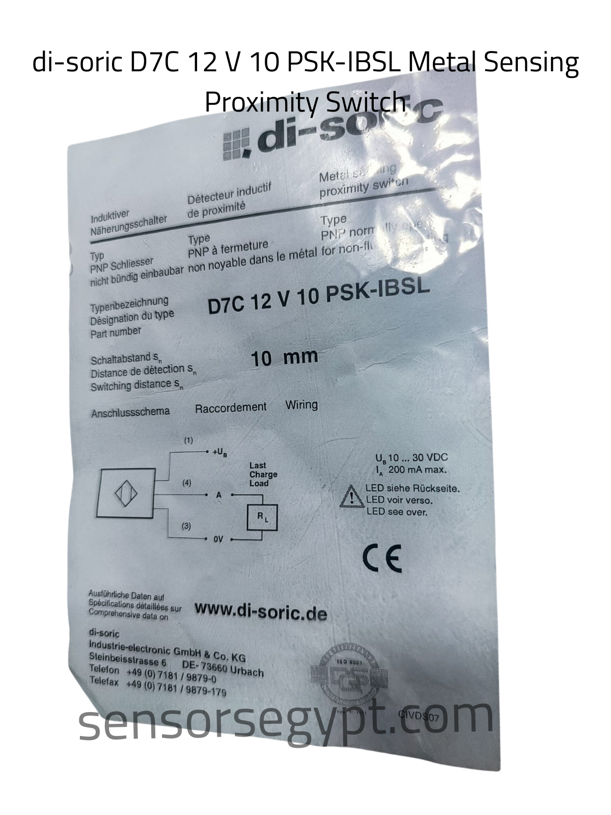
Part Number / Type: D7C 12 V 10 PSK-IBSL
Product Category: Metal Sensing Proximity Switch (Induktiver Näherungsschalter)
1. Product Characteristics & Application
-
Sensor Type: Inductive Proximity Sensor
-
Housing Design: Threaded cylindrical barrel type (M12 designator indicated by the
12in the part number). -
Sensing Range (sn): 10 mm (Extended high-performance range for its housing diameter).
-
Mounting: Non-flush mountable (indicated by the label text: nicht bündig einbaubar / non noyable dans le métal / for non-flush mounting).
-
Special Features: Part of di-soric’s reliable high-performance proximity line, engineered for contactless metal target verification. Its generous 10 mm non-flush sensing window allows it to remain at a safe clearance from moving machine targets, making it ideal for robust factory automation, conveyor sorting systems, and material position loop monitoring.
2. Electrical Data
-
Operating Voltage (UB): 10…30 V DC
-
Rated Operational Current (IA): ≤ 200 mA max.
-
Electrical Design: DC PNP
-
Output Function: Normally Open (NO) (indicated by: PNP Schliesser / PNP à fermeture / PNP normally open).
-
Approvals: CE, ISO 9001 certified manufacture template.
3. Performance & Indicators
-
Status Indicator: Integrated LED feedback indicator loop (LED siehe Rückseite / LED voir verso / LED see over).
-
Short-Circuit & Reverse Polarity Protection: Yes
-
Switching Frequency: High responsive cyclic velocity optimized for rapid automation tracking, indexing steps, and dynamic feedback circuits.
4. Mechanical & Environmental Data
-
Dimensions: M12 standard industrial metric threads
-
Housing Material: Premium rugged metal alloy casing with high mechanical wear resistance.
-
Ambient Operating Temperature: Standard industrial resilience profile.
-
Manufacturer Location: di-soric Industrie-electronic GmbH & Co. KG | Steinbeisstrasse 6, DE-73660 Urbach, Germany.
-
Code References: CIVDS07
5. Electrical Connection & Wiring Layout
The sensor utilizes a 3-pin operational output interface configuration via an integrated standard plug terminal connection.
Pinout Assignment:
-
Pin 1: Brown wire reference → +UB (10…30 V DC Power Supply Input)
-
Pin 4: Black wire reference → A (Active Switching Output Signal to Load)
-
Pin 3: Blue wire reference → 0V (Ground / Common line)
Wiring Diagram:
Plaintext
       [ Pin 1 ] ───────────────────────── ( + UB )
          │
      ┌───┴───┐
      │  PNP  │───────── [ Pin 4 ] ──── [ Load ] ────┐
      │  N.O. │                                      │
      └───┬───┘                                      │
          │                                          │
       [ Pin 3 ] ────────────────────────────────────┴─── ( 0V ) DATA SHEET
Reviews
There are no reviews yet.